Palladio 400/500 RPL


Depending on the configuration and following revisions, the features of the board are subject to change. For detailed information on hardware specifications, please visit www.seco.com
SECO Palladio 400/500 RPL are modular fanless embedded PC with 13th Gen Intel® Core™ processors (formerly known as Raptor Lake-P).
For ordering purposes, the Palladio 400/500 RPL are referred to by their base codes, “SF-K840-RPL” and “SF-K850-RPL“.
Technical Documents
At the following Links you will find documentations like Manual and Rev. specific documents.
Manual
Datasheet
Product page
How can I update BIOS?
To update the BIOS, you can download the latest version of the package from the Downloads section below and use the correct package for the Palladio system you have to follow the instructions in the following file:
Please pay attention to choose the correct update utility for your product, the table below depicts which BIOS version corresponds to the SECO products that you have purchased:
| SECO PN | MODEL |
|---|---|
| SF-K840-RPL-01-00 | SECO-K843-PALLADIO400RPL |
| SF-K840-RPL-02-00 | SECO-K845-PALLADIO400RPL |
| SF-K840-RPL-03-00 | SECO-K847-PALLADIO400RPL |
| SF-K850-RPL-01-00 | SECO-K855-PALLADIO500RPL |
| SF-K850-RPL-02-00 | SECO-K857-PALLADIO500RPL |
| SF-K850-RPL-03-00 | SECO-K859-PALLADIO500RPL |
Downloads
The following are links to the current software releases:
| Package | Download |
|---|---|
| Palladio 400 - BIOS package | Palladio_400_bios_utility.7z |
| Palladio 500 - BIOS package | Palladio_500_bios_utility.7z |
| WIN11 LTSC drivers | seco_raptorlakep_palladio_drivers_win11.7z |
Clea OS
Clea OS is a versatile and robust Linux Operating System framework designed specifically for industrial embedded devices. Based on the open source Yocto Project, Clea OS offers a flexible and customizable platform that can be tailored to meet the specific needs of various hardware architectures and applications.
Starting with Linux Kernel 5.10, the Board Support Package (BSP) for this board is fully integrated into Clea OS. It ensures high security and stability through features like OTA (Over-the-Air) updates, dual partitions, and fallback procedures. Additionally, Clea OS includes a complete device manager for seamless cloud communication, enabling centralized management of product fleets.
Documentation
For a complete explanation of Clea OS and detailed installation instructions, refer to the official documentation:
Download Clea OS Images
To quickly get started, download the latest complete prebuild Clea OS images (or other binaries like U-Boot, Linux Kernel, SDKs) from the official release page:
Download Clea OS images here - Release Page
Installation instructions for Intel Boards
Build Clea OS
The source code for Clea OS can be found at the following Gitlab organization. To build a complete BSP image from source you can check the Get Started pages of the documentation.
Frequently Asked Questions (FAQ)
How do I enable auto power on?
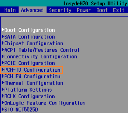
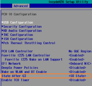
Enter the BIOS and go to Advanced > PCH-IO Configuration > State After G3. Set it to [s0 State]. See below for a step by step guide.
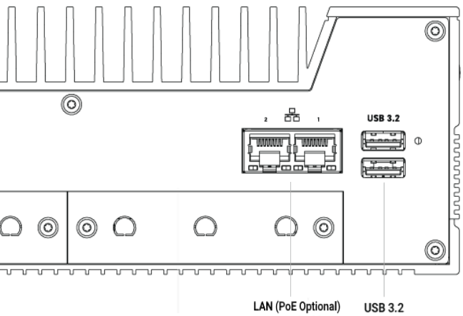
Which LAN ports support PoE?
The K800 can be configured with optional PoE hardware, adding PoE functionality to existing ports, or adding additional PoE ports. Check your configuration to see if your unit has PoE installed.
The optional PoE module supports the 802.3at standard @ up to 25.5 watts per port.
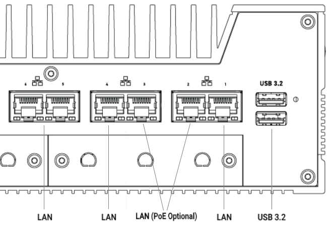
PoE can be added to the native Ethernet ports on either ports 1 & 2 (on the x2
LAN models), or ports 2 & 3 (on the x6 LAN models). Additional ports may be
added with the Karbon Modbay cards.
K800 series 2-LAN model:
K800 series 6-LAN model:
What Operating Systems are supported?
Windows 10 IoT 2021 and Windows 11 are supported. In most applications it is NOT necessary to disable the e-cores.
The K800 also supports Ubuntu 22.04 for Intel IoT with Kernel version 5.15. Other Ubuntu and Kernel versions are not supported on the K800 series.
What chipset do the Ethernet ports uses?
The onboard LAN ports use the I225. The optional 10gig Modbay expansion card uses the X550.
What Baudrate is supported on the K800 COM ports?
The K800 series supports up to 115200 baudrate on the COM ports. Higher baud rates can be achieved by implementing the CAN port. See how to do this through the Embedded Microcontroller MCU in the CAN section below.
How do I disable TurboBoost on the CPU?
TurboBoost can be disabled in the BIOS of the system. Navigate to Advanced
and set Expert Mode to Enabled. Then, go to:
Power & Performance -> CPU – Power Management Control -> Boot
Performance -> Set to Max Non-Turbo Performance
How do I use the integrated video ports, instead of the GPU?
The K800 series can be configured with a GPU. For some customers this is used to drive multiple high-resolution displays, and the video output will automatically output through the GPU. However in some cases you may want to use the GPU for specific computational applications, and use the integrated DisplayPorts. To enable this option, you will want to change the “Primary Display” output in the BIOS. Navigate to:
**Setup Utility - > Advanced page- > **Set “Expert Mode” to
Enabled
Then go to:
**Setup Utility - > Advanced -> System Agent (SA) Configuration -> Graphics
Configuration -> Primary Display -> **Change to “IGFX”
Make sure to Save & Reset via the F10 function key or through the Exit
page.
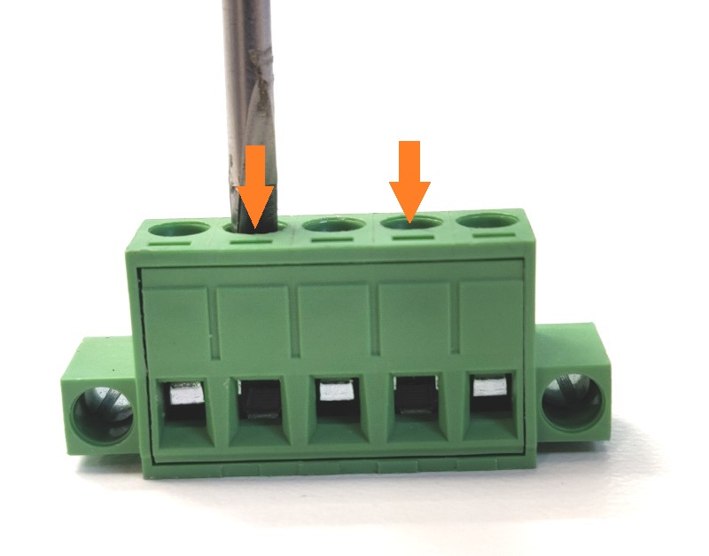
Connecting the power supply
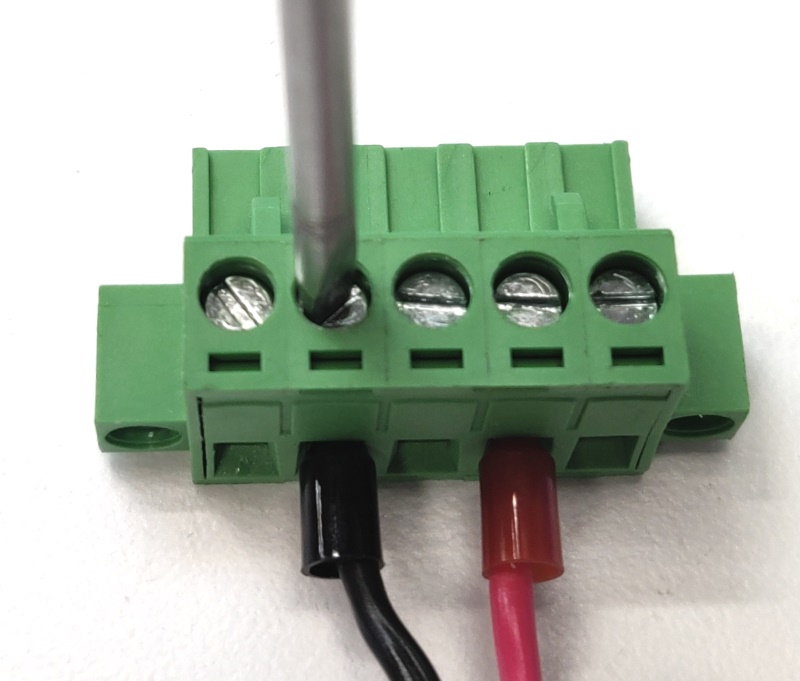
If you need to assemble the system’s power input connector, follow these steps to locate and wire the correct parts.
-
Unbox the power brick and grab the 5 pin green/black terminal block from the accessory box.
-
Using a flathead screwdriver, turn the two indicated screws counter-clockwise a few turns.
-
The metal holes at the bottom will open up.
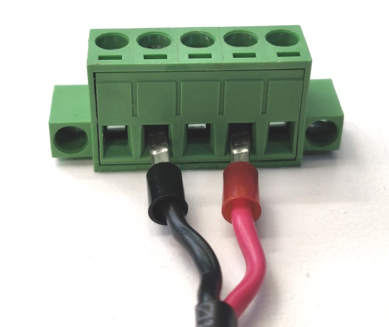
- Insert the power supply wires as shown
-
Turn the screws clockwise to tighten. Firmly hand tighten.
-
Connect the green/black terminal block to the Palladio. It is now ready for use. Note that the labeling on the back of the system matches the wires you just installed.
Enabling Auto Power On
The Palldio can be configured to turn on automatically when DC power is connected. This is useful for power outage recovery or if the unit is mounted in a hard to reach location. You can enable Auto Power On by following the steps listed below.
- Note: In future revisions the name of this setting will be changed. “Auto power ON’ under the Power tab will be the new name and location.
-
Power on the system and press Del a few times to access the “Front Page” menu
-
Choose “Setup Utility”
-
Navigate to Advanced > PCH-IO Configuration
-
Locate “State After G3”
-
Change it to”s0 State” to enable auto power on.
- Press F10 to Save & Exit
Accessing the Microcontroller (MCU)
The embedded microcontroller unit (MCU) is used to interface and control various aspects of the system such as CAN, DIO, and ignition sensing. To communicate with the MCU, follow the steps below for your installed OS.
Windows
-
Download the PuTTy tool from putty.org
-
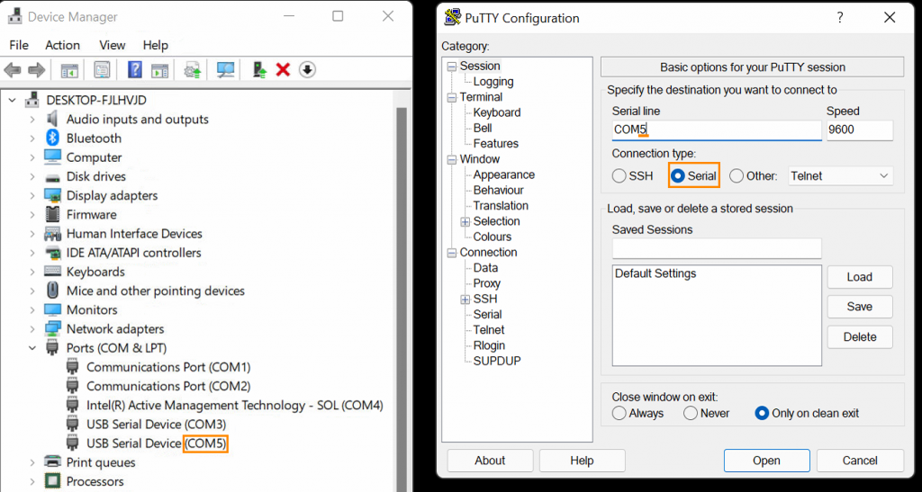
Look in Device Manager and find the highest numbered USB serial device, COM5 in this example
-
Open Putty. Set the connection type to Serial and change COM1 to the COM # you found in the previous step. This example uses COM5.
-
Click “Open”. This will open a virtual connection to the MCU (no physical cable is required)
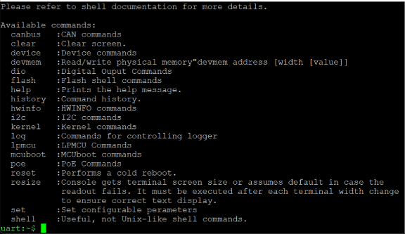
- To confirm you have the correct port open, type “help” and press enter. The help text should appear. If it does not, try a different COM port.
Linux
-
Use a program such as PuTTy to interface with the microcontroller (MCU). You can run the following command to install it (you will need an active internet connection for this):
sudo install putty
-
The MCU will typically enumerate as
ttyACM0. It enumerates as a serial-interfaceable USB device. If you run into issues accessingttyACM0, you can run the following command to identify the other port(s):sudo dmesg | grep tty
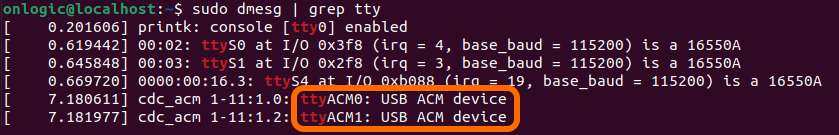
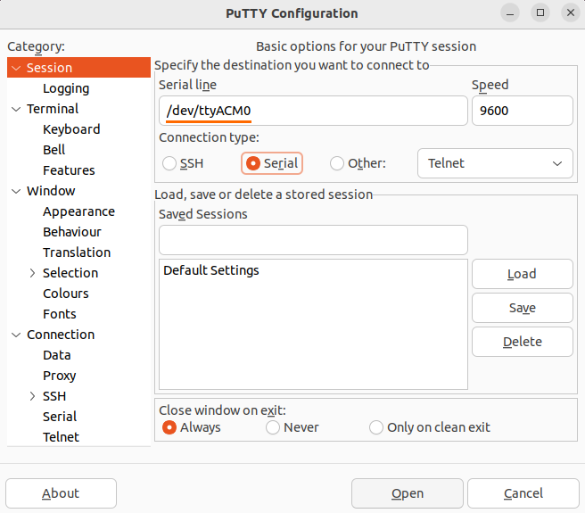
- In this example, the MCU is on
ttyACM0. Open PuTTy, enter the port #, and set the connection type as “Serial”. The other settings can be left on their defaults (i.e. baudrate = 9600).
- To confirm you have the correct port open, type “help” and press enter. The help text should appear. If it does not, try a different port #.

Microcontroller Commands
A full list of microcontroller commands be be found here in the User MCU Shell documentation here: