Modular Vision QCS6490
Introduction
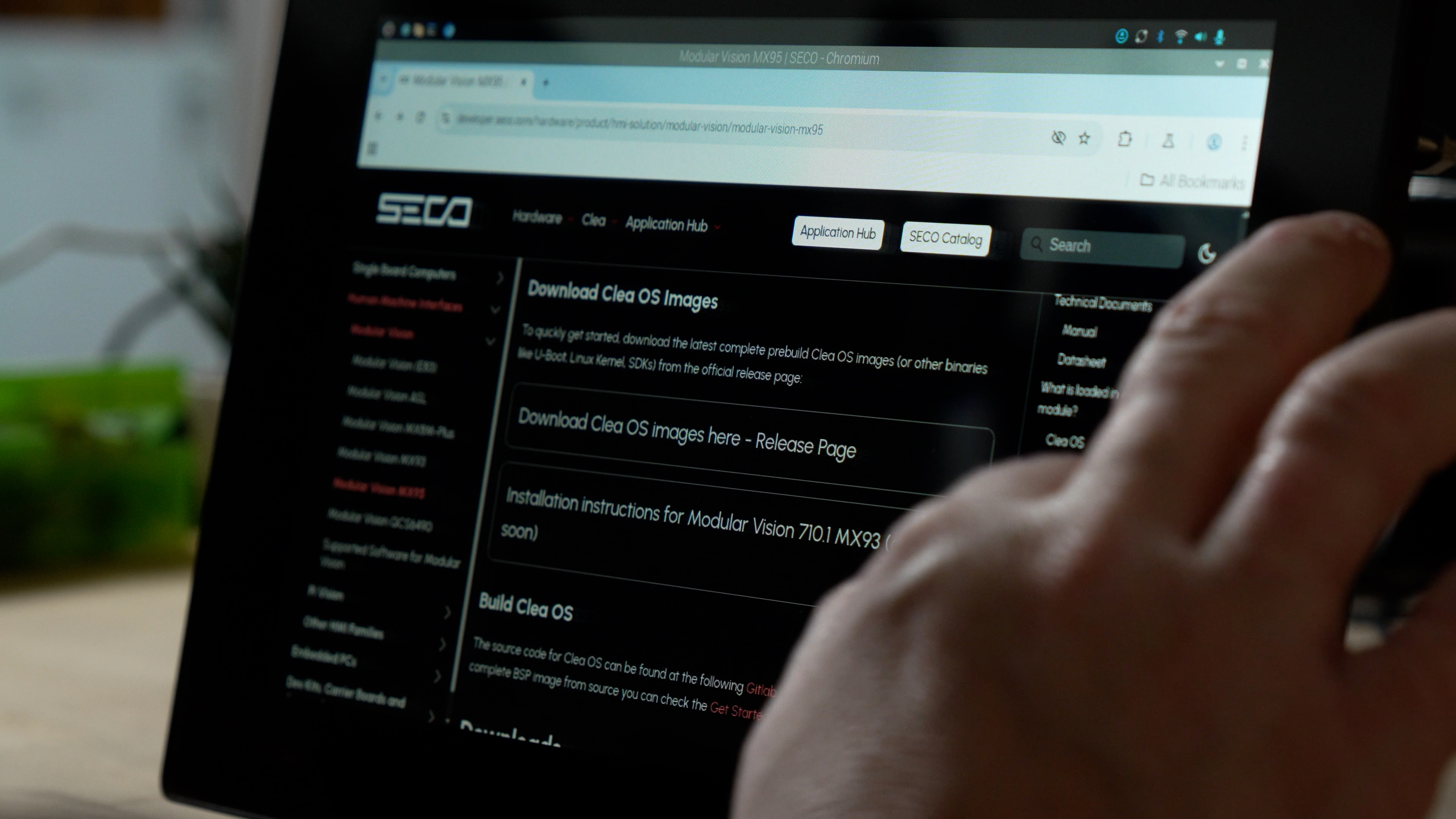
Welcome to the quick start guide for SECO’s Modular Vision QCS6490, an all in one industrial HMI solution available in 10.1 inch and 15.6 inch formats. This platform combines:
- Qualcomm QCS6490 application processor with Arm Cortex A78 and Cortex A55 cores,
- Adreno 643L GPU for advanced graphics and UI,
- Projected capacitive touch display with chemically strengthened cover glass,
- Integrated industrial connectivity, including Ethernet, serial interfaces and digital I/O,
- Clea OS as the default operating system, with support for containers and remote device management through the Clea framework.
Modular Vision QCS6490 is designed for use cases such as smart kiosks, vending, industrial automation, medical devices and building automation, where a robust panel HMI with ready to use compute and connectivity is required.
What's in the Box
The exact content of the package depends on the ordering code and the configuration of your kit. As a reference, a typical delivery for Modular Vision QCS6490 includes:
- 1 x Modular Vision QCS6490 HMI unit (10.1 inch or 15.6 inch variant)
- 1 x set of mounting points compatible with standard mechanical fixtures (for example VESA or panel mounting holes, as per datasheet and mechanical drawings)
- 1 x documentation set, including safety and installation manual (digital or printed, depending on configuration)
Additional accessories, such as power supply, cables or brackets, may be included depending on the commercial offering and the specific kit you purchased. Always refer to your order confirmation and packing list for the exact scope of supply.
Before You Start
Requirements
To follow this getting started guide you will need:
- Modular Vision QCS6490 unit
- 10.1-inch or 15.6 inch version, both based on the Qualcomm QCS6490 processor
- Regulated DC power supply, compliant with the voltage and current specifications indicated in the latest Modular Vision QCS6490 datasheet and installation manual
- A host PC or laptop for development and testing, with
- Ethernet interface for network connection to the HMI
- Optionally, USB ports if you plan to connect keyboard, mouse or other USB devices
- Cables and accessories, for example
- DC power cable, wired to the Modular Vision power connector as specified in the manual
- Ethernet cable (twisted pair, Cat5e or better)
- Optional cables for serial interfaces, digital I/O, CAN or external peripherals, following the connector pinouts in the manual
- Basic tools for mounting the device, such as screws and screwdriver, matching the mechanical drawings and mounting pattern of your chosen installation (panel, arm or wall mount)
Make sure you have also downloaded the latest:
- Datasheet for Modular Vision 10.1 QCS6490 and/or Modular Vision 15.6 QCS6490
- Modular Vision installation and warnings manual
- Any Clea OS release notes or documentation relevant to your image version
Safety & Handling
Before powering or installing the Modular Vision QCS6490, carefully read the safety chapter in the official Modular Vision manual. In particular:
- Respect the indicated power supply range and polarity
- Ensure that the device is properly grounded, according to your local regulations and the manual
- Avoid exposing the device to environments outside the specified operating temperature range
- Do not open the enclosure or modify the device, unless explicitly allowed by the documentation and by SECO
- Use only dry cleaning methods as indicated in the maintenance section of the manual, and always disconnect power before any cleaning or maintenance activity
Mechanical Installation
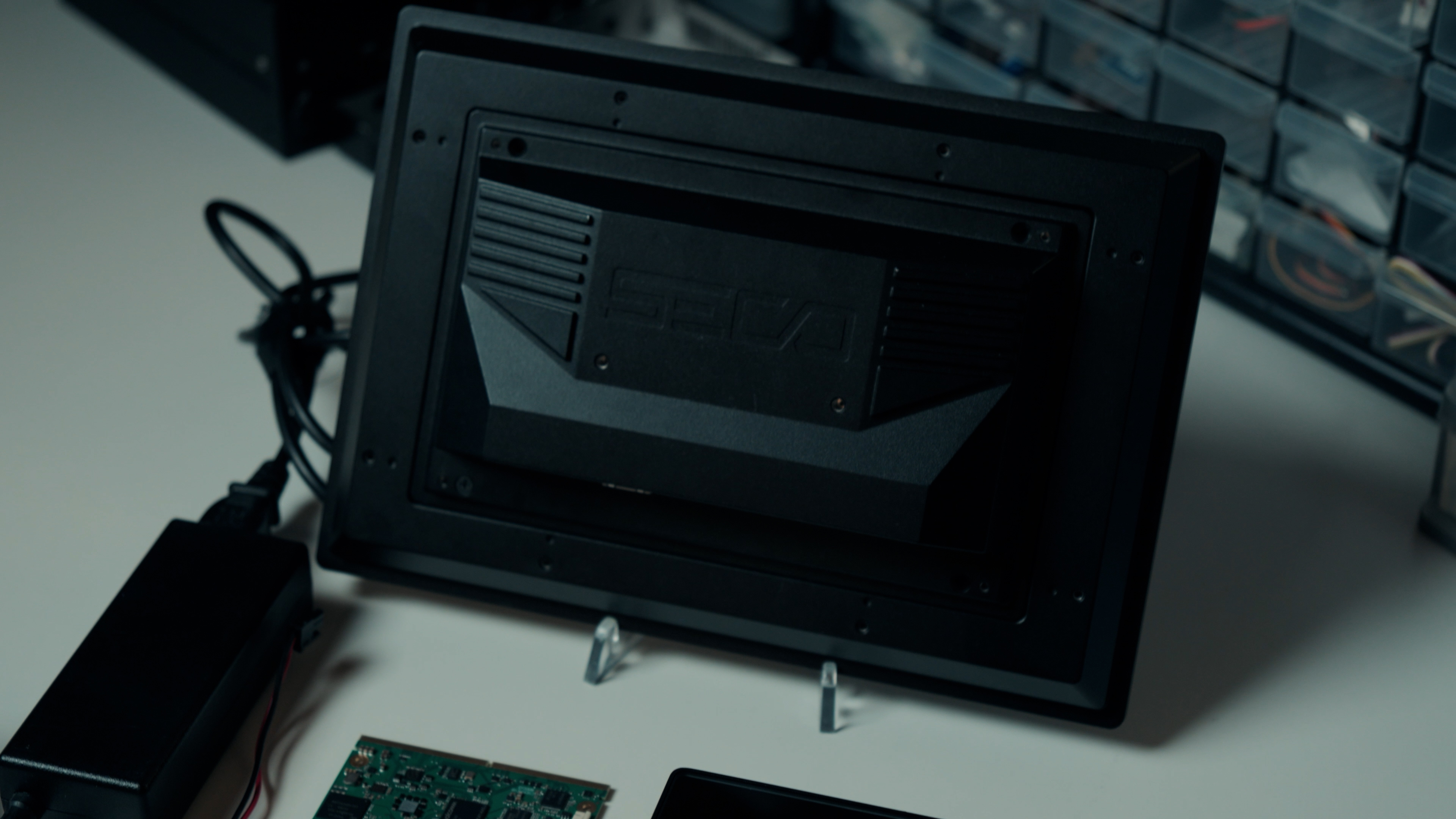
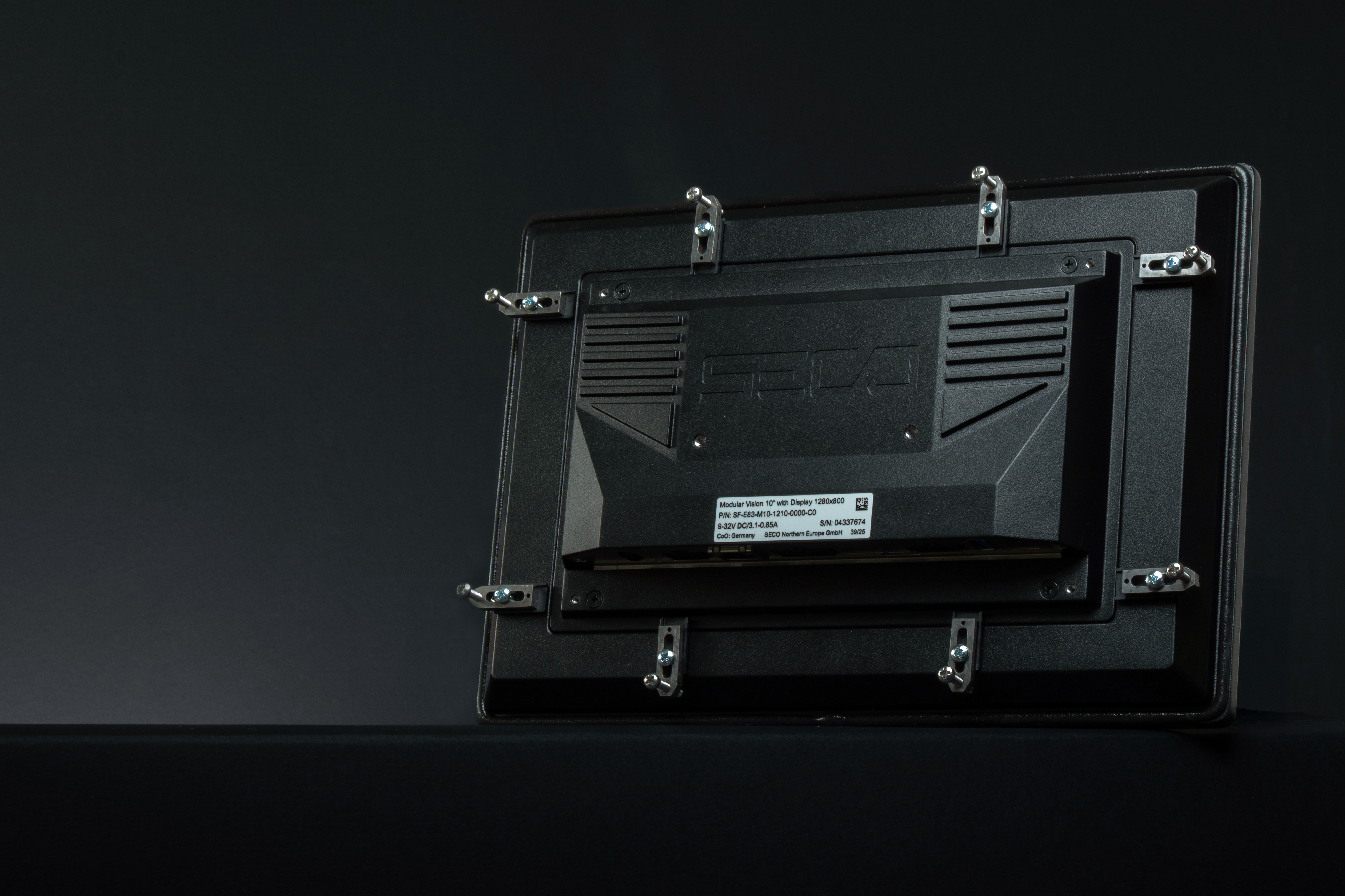
Modular Vision QCS6490 is designed as a panel or arm mounted HMI. The device provides mechanical mounting points on the rear enclosure, compatible with standard supports as specified in the datasheet and mechanical drawings. Typical mounting scenarios include:
- Panel mounting on a machine front door or operator panel
- Wall mounting or arm mounting through VESA compatible brackets
- Integration in custom frames or housings designed around the provided hole pattern and device thickness
Follow this general procedure, in combination with the detailed mechanical drawings in the datasheet:
- Ensure that power to the destination machine is switched off and disconnected.
- Identify the mounting pattern on the back of the Modular Vision unit and on the target surface or bracket.
- Use fasteners that match the specified thread type and length, paying attention to the maximum torque and avoiding stress on the enclosure.
- Make sure that the device is correctly seated and that no mechanical stress is applied to the display front or to the connectors.
- Once the device is mechanically secured, proceed with the electrical connections as described in the next sections.
Hardware Overview
Modular Vision QCS6490 integrates display, compute board, touch panel and I/O in a single enclosure. Key hardware elements include:
-
Processor and Memory
- Qualcomm Dragonwing QCS6490 application processor with a combination of Arm Cortex A78 and A55 cores
- Soldered down LPDDR5 memory, up to 8 GB total, for robust and vibration tolerant operation
-
Display and touch:
- 10.1″ version
- Resolution 1280 × 800, LED backlight with industrial lifetime and typical brightness of 400 cd/m²
- 15.6″ version
- Resolution 1920 × 1080, LED backlight with typical brightness of 400 cd/m²
- Both formats use projected capacitive touch with approx. 3.0 mm chemically strengthened cover glass for robust front protection.
- 10.1″ version
-
Mass storage:
- On-board eMMC 5.1 used as primary boot device, with configurations up to 64 GB.
- SD interface and microSD card holder available for removable storage and alternative boot options, depending on software configuration.
-
Power input: DC input on a dedicated power connector, supporting a nominal range from 9 VDC to 32 VDC as specified in the datasheets and installation manual.
-
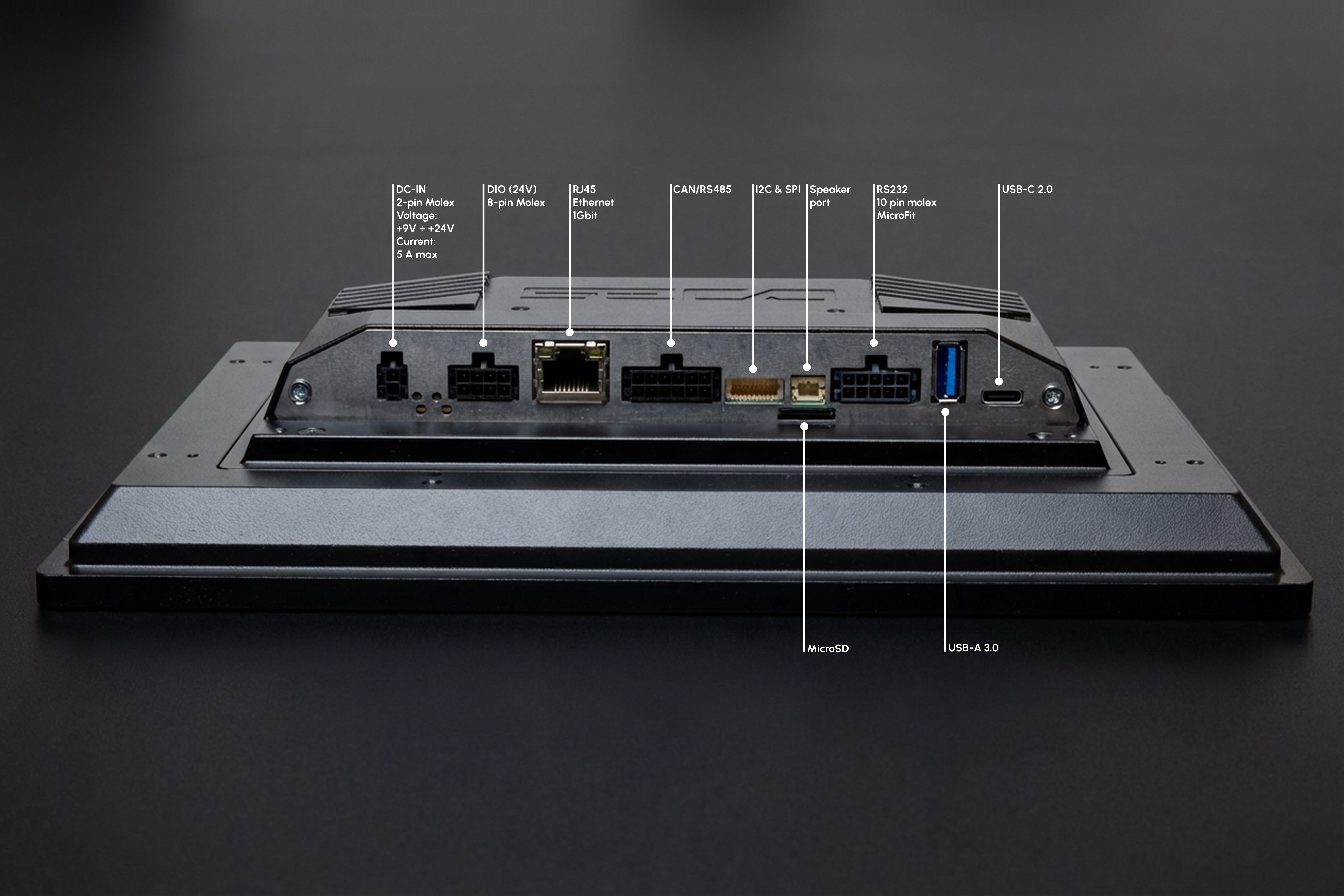
Connectivity and I/O: Connector numbering follows the Modular Vision installation manual.
- 01 – Power: main DC input to supply the HMI.
- 02 – Power LED: indicates presence of input power.
- 03 – Reset switch: triggers a hardware reset of the system.
- 04 – Status LED: provides visual feedback on system status.
- 05 – Clearall switch: used to start a software-controlled cleaning or reset procedure, as documented in the manual.
- 06 – Digital I/O: Micro-Fit connector providing configurable digital inputs and outputs within the voltage levels indicated in the manual.
- 07 – Ethernet: RJ45 Gigabit Ethernet port with integrated LEDs for link and speed indication.
- 08 – CAN/RS485 interface: Micro-Fit connector exposing CAN-FD and RS-485 signals, with selectable termination as per wiring tables.
- 09 – Keypad/SPI: JST SHD connector for external keypad or SPI-based peripherals.
- 10 – SD-card reader: slot for SD media used by the system according to the selected software setup.
- 11 – Speaker: JST PH connector for mono speaker output.
- 12 – RS232 / MDB: Micro-Fit connector exposing serial ports, including RS-232 and optional MDB interface, as defined in the manual.
- 13 – USB-Host: USB Type-A host port (USB 3.0 on 10.1″, USB 2.0 on 15.6″).
- 14 – USB-OTG: USB Type-C 2.0 Dual Role interface.
For any wiring or integration activity, always cross-check the latest pinout tables and electrical specifications in the official Modular Vision manual and QCS6490 datasheets.
First Boot & OS Setup
-
Connect Power and Peripherals
- Place the Modular Vision QCS6490 HMI in its intended position, ensuring that all interfaces are accessible.
- Connect the regulated DC power cable to the power input connector, following the voltage range and polarity specified in the latest datasheet.
- Connect an Ethernet cable to the Gigabit Ethernet port if network access is required.
- Optionally connect a USB keyboard and mouse to the available USB ports for local interaction.
-
First Power-On
- Switch on the external power supply.
- Verify that the device powers up, the status indicators turn on and the display starts the boot sequence.
- Wait until the Clea OS login screen or graphical interface is fully loaded.
-
Operating System
- Log in using the credentials defined for your project or image.
- From the Clea OS environment, verify basic settings such as network configuration, date and time.
- If configuration tools are available in the image, use them to align hostname, time zone and other core parameters with your infrastructure.
-
Test and Evaluate
- Use the touch screen and any connected peripherals to confirm that display and input are working correctly.
- If demo or sample applications are preinstalled, launch them to validate the main HMI functions and basic performance.
-
Recovery or Reflashing
- When you need to update or reinstall the software image, use the official procedures provided in the Clea OS and Developer Center documentation for Modular Vision.
- After the update or reflash is completed, repeat the steps in this section from “Connect Power and Peripherals” to confirm that the unit boots correctly with the new image.
Power and Thermal Considerations
When integrating Modular Vision QCS6490 into your system, consider the following:
Power supply
- Use a regulated DC power supply that is compliant with the voltage and power ranges specified in the latest Modular Vision QCS6490 datasheets and installation manual.
- Ensure that wiring, connectors and fuses in your system are dimensioned for the maximum current draw.
Thermal design
- Operate the device within the indicated ambient or heatspreader temperature range.
- Avoid installing the device in fully enclosed spaces without ventilation, unless a proper thermal design evaluation has been performed.
- Do not cover ventilation openings, and avoid direct exposure to intense heat sources.
Environmental conditions
- Respect any IP rating and environmental conditions defined for the device.
- Protect the front glass from mechanical impacts that exceed the specified limits.
If your application involves harsh environments, high duty cycle workloads or continuous 24/7 operation, consider performing thermal testing in the target enclosure to confirm that all limits are respected.
Next Steps & Resources
- Full documentation and manuals are available on the Developer Center HERE
- For software guides and Clea OS instructions, refer to the CleaOS documentation.
- For full guides on device management, refer to Clea Device Manager User Guide.
- For full documentation on how to connect a device to Clea, refer to Clea device connection guide.
- A QR code inside the kit (if purchased as DEV-KIT-SMARC) links to additional resources and quick start videos.
Support
Need help? Visit www.seco.com or contact SECO Technical Support for drivers, software tools, and integration support.